Your First Cisco Topology
Introduction
This document explains how to configure a simple GNS3 topology consisting of two Cisco routers. The set up shown here is the same when using either a local GNS3 installation or a GNS3 VM environment.
This document assumes that you already have GNS3 installed and a Cisco IOS router image added to GNS3. If not, please refer to other guides which explain how to download, install and configure GNS3.
Create your Topology
- To create a new GNS3 topology, select a group of devices in the Devices Toolbar by clicking the device type button. In this example the Routers group was selected:
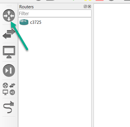
- In this example, a c3725 IOS image has already been imported, so we’ll use it.
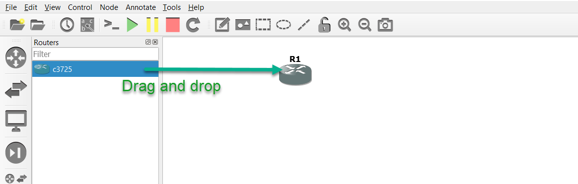
- Drag and drop the selected node (device) to the GNS3 Workspace. An instance of the node becomes available in the Workspace. In this example a router is now available:
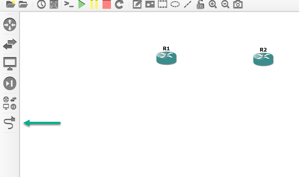
- Drag and drop the node again into the GNS3 Workspace, which will result in routers R1 and R2 appearing in both the Workspace, and the Topology Summary:

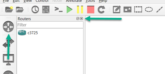
- Click the Toolbar Device button again (or the X in the corner of it) to collapse the group:
- Click the Add a Link button to start adding links to your topology. The mouse cursor will change to indicate that links can be added:
- Click on a device in your topology to display available interfaces. In this example we’ll use FastEthernet0/0 of each router to connect them together:
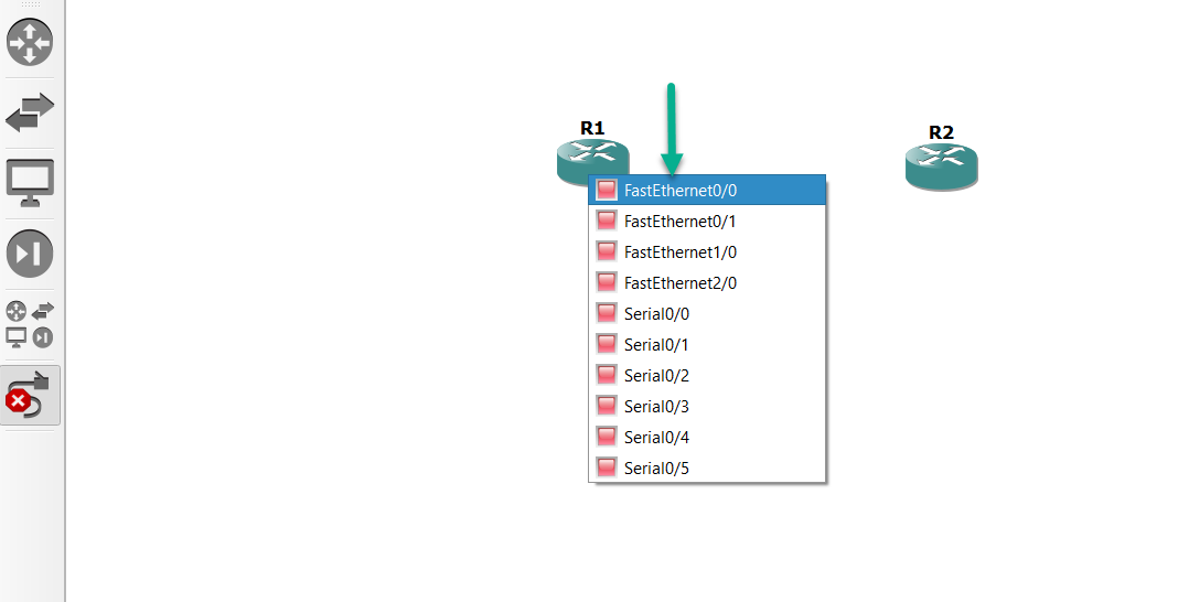
- Left click FastEthernet0/0 of R1, and connect it to FastEthernet0/0 of R2.

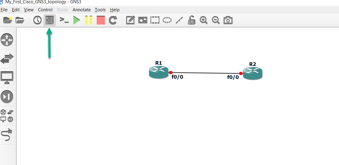
- Click the Interface Names icon (this is optional), to display the interfaces on each device, that have been connected together.
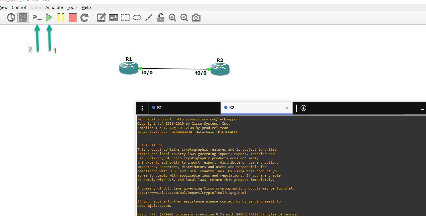
Below, the green Start button (marked #1) and the Console button (marked #2) have been selected. This powers on all devices in the Workspace, as well as launches Solar-Putty and creates tabs for each device:
Now let’s configure the routers!
Since these are IOS images, they will act like real routers, as you’ll see.
After R1 loads up, we’ll already be at the enable prompt, due to the configuration files GNS3 includes (they also configure “logging sync” and “exec-time 0 0” on line con 0 for us, and let us bypass that initial configuration dialog). Let’s look at the interfaces of R1:
R1# sh ip int br
Interface                  IP-Address      OK? Method Status                Protocol
FastEthernet0/0            unassigned      YES unset  administratively down down
Serial0/0                  unassigned      YES unset  administratively down down
FastEthernet0/1            unassigned      YES unset  administratively down down
Serial0/1                  unassigned      YES unset  administratively down down
Serial0/2                  unassigned      YES unset  administratively down down
Serial0/3                  unassigned      YES unset  administratively down down
Serial0/4                  unassigned      YES unset  administratively down down
Serial0/5                  unassigned      YES unset  administratively down down
FastEthernet1/0            unassigned      YES unset  administratively down down
FastEthernet2/0            unassigned      YES unset  administratively down down
R1#
As you can see, the interfaces are all administratively down/down. The same is true of R2:
R2# sh ip int br
Interface                  IP-Address      OK? Method Status                Protocol
FastEthernet0/0            unassigned      YES unset  administratively down down
Serial0/0                  unassigned      YES unset  administratively down down
FastEthernet0/1            unassigned      YES unset  administratively down down
Serial0/1                  unassigned      YES unset  administratively down down
Serial0/2                  unassigned      YES unset  administratively down down
Serial0/3                  unassigned      YES unset  administratively down down
Serial0/4                  unassigned      YES unset  administratively down down
Serial0/5                  unassigned      YES unset  administratively down down
FastEthernet1/0            unassigned      YES unset  administratively down down
FastEthernet2/0            unassigned      YES unset  administratively down down
R2#
Let’s configure interface fa0/0 and loopback0 of R1:
R1# conf t
Enter configuration commands, one per line.  End with CNTL/Z.
R1(config)# int fa0/0
R1(config-if)#ip add 10.1.1.1 255.255.255.0
R1(config-if)#int loop 0
R1(config-if)#ip add
*Mar  1 00:03:42.663: %LINEPROTO-5-UPDOWN: Line protocol on Interface Loopback0, changed state to up
R1(config-if)#ip add 1.1.1.1 255.255.255.255
R1(config-if)# end
R1#sh ip int br
Interface                  IP-Address      OK? Method Status                Protocol
FastEthernet0/0            10.1.1.1        YES manual administratively down down
Serial0/0                  unassigned      YES unset  administratively down down
FastEthernet0/1            unassigned      YES unset  administratively down down
Serial0/1                  unassigned      YES unset  administratively down down
Serial0/2                  unassigned      YES unset  administratively down down
Serial0/3                  unassigned      YES unset  administratively down down
Serial0/4                  unassigned      YES unset  administratively down down
Serial0/5                  unassigned      YES unset  administratively down down
FastEthernet1/0            unassigned      YES unset  administratively down down
FastEthernet2/0            unassigned      YES unset  administratively down down
Loopback0                  1.1.1.1         YES manual up                    up
R1#
That’s just like a real router. We have to enable the interface first, before it will come up (virtual interfaces like loopback0 automatically get enabled when we create them. SVIs on switches are a little different, since they need to be associated with either an access port or trunk port before they come up).
Let’s enable fa0/0 on R1:
R1(config)#int fa0/0
R1(config-if)#no shut
R1(config-if)#end
R1#
*Mar  1 00:06:52.391: %SYS-5-CONFIG_I: Configured from console by console
R1#sh
*Mar  1 00:06:52.667: %LINK-3-UPDOWN: Interface FastEthernet0/0, changed state to up
*Mar  1 00:06:53.667: %LINEPROTO-5-UPDOWN: Line protocol on Interface FastEthernet0/0, changed state to up
There we go! That’s more like it! Now let’s check those interfaces again:
R1#sh ip int br
Interface                  IP-Address      OK? Method Status                Protocol
FastEthernet0/0            10.1.1.1        YES manual up                    up
Serial0/0                  unassigned      YES unset  administratively down down
FastEthernet0/1            unassigned      YES unset  administratively down down
Serial0/1                  unassigned      YES unset  administratively down down
Serial0/2                  unassigned      YES unset  administratively down down
Serial0/3                  unassigned      YES unset  administratively down down
Serial0/4                  unassigned      YES unset  administratively down down
Serial0/5                  unassigned      YES unset  administratively down down
FastEthernet1/0            unassigned      YES unset  administratively down down
FastEthernet2/0            unassigned      YES unset  administratively down down
Loopback0                  1.1.1.1         YES manual up                    up
R1#
And as expected, fa0/0 is up/up. Let’s configure the interfaces on R2 next:
R2#conf t

Enter configuration commands, one per line.  End with CNTL/Z.

R2(config)#int fa0/0
R2(config-if)#no shut
R2(config-if)#

*Mar  1 00:00:36.899: %LINK-3-UPDOWN: Interface FastEthernet0/0, changed state to up
*Mar  1 00:00:37.899: %LINEPROTO-5-UPDOWN: Line protocol on Interface FastEthernet0/0, changed state to up

R2(config-if)#ip add 10.1.1.2 255.255.255.0
R2(config-if)#int loop 0
R2(config-if)#

*Mar  1 00:00:53.215: %LINEPROTO-5-UPDOWN: Line protocol on Interface Loopback0, changed state to up

R2(config-if)#ip add 2.2.2.2 255.255.255.25
Bad mask 0xFFFFFF19 for address 2.2.2.2
R2(config-if)#ip add 2.2.2.2 255.255.255.255
R2(config-if)#
Since we used “no shut” on int fa0/0 already, that interface has already gone up/up, and loopback0 went up/up as soon as we created that interface. But notice that error I’ve bolded, where I entered the /32 subnet mask incorrectly. This is an IOS image off a real router, and as such, mistakes you make will cause the router to output messages letting you know something is amiss.
If we run “sh version” on R2, we can see the image it’s using, just like a physical router will:
R2#sh ver

Cisco IOS Software, 3700 Software (C3725-ADVENTERPRISEK9-M), Version 12.4(15)T14, RELEASE SOFTWARE (fc2)

Technical Support: http://www.cisco.com/techsupport
Copyright (c) 1986-2010 by Cisco Systems, Inc.
Compiled Tue 17-Aug-10 12:08 by prod_rel_team
ROM: ROMMON Emulation Microcode
ROM: 3700 Software (C3725-ADVENTERPRISEK9-M), Version 12.4(15)T14, RELEASE SOFTWARE (fc2)
....truncated for brevity.......
I truncated the output, but you can can see the router knows it’s running an advanced enterprise c3725 image, along with the version number.
Since I quickly corrected my mistake, let’s see if the routers can ping one other, via the IP address assigned to their fa0/0 interfaces:
At this point, R2 should be able to ping R1, which it can.
R2#ping 10.1.1.1
Type escape sequence to abort.
Sending 5, 100-byte ICMP Echos to 10.1.1.1, timeout is 2 seconds:
.!!!!
Success rate is 80 percent (4/5), round-trip min/avg/max = 20/27/32 ms
R2#
(that single missed ping was due to the initial ARP broadcast, which is normal).
R1 should also be able to ping R2, which it can:
R1#ping 10.1.1.2
Type escape sequence to abort.
Sending 5, 100-byte ICMP Echos to 10.1.1.2, timeout is 2 seconds:
!!!!!
Success rate is 100 percent (5/5), round-trip min/avg/max = 4/8/12 ms
R1#
(there's no dropped ping, since the ARP exchange already took place).
As expected, pings succeed. Now, because the routers don’t contain routes to the /32 addresses assigned to each others loopback0 interfaces, let’s use a routing protocol (ospf in this instance), so they can each dynamically learn how to reach those:
R1(config)#router ospf 1
R1(config-router)#router-id 1.1.1.1
R1(config-router)#network 0.0.0.0 255.255.255.255 area 0
R1(config-router)#end
R1#
(note: using "network 0.0.0.0 255.255.255.255 area 0" in ospf is a shortcut to enable ospf on all interfaces in an ospf area. It's not always desirable in the real world, but is fine for lab purposes)
Let’s do the same on R2L
R2#conf t
Enter configuration commands, one per line.  End with CNTL/Z.
R2(config)#router ospf 1
R2(config-router)#router-id 2.2.2.2
R2(config-router)#network 0.0.0.0 255.255.255.255 area 0
R2(config-router)#end
R2#
*Mar  1 00:15:54.155: %OSPF-5-ADJCHG: Process 1, Nbr 1.1.1.1 on FastEthernet0/0 from LOADING to FULL, Loading Done
R2#
*Mar  1 00:15:57.271: %SYS-5-CONFIG_I: Configured from console by console
R2#
(notice that an ospf neighbor relationship between R1 and R2 has already formed)
R2#sh ip ospf neigh
Neighbor ID     Pri   State           Dead Time   Address         Interface
1.1.1.1           1   FULL/DR         00:00:34    10.1.1.1        FastEthernet0/0
R2#
Running this command on R2 proves that not only was the relationship formed, but it’s in the FULL state, as opposed to 2WAY or EXSTART.
Now let’s check the routing table on R1:
R1#
*Mar  1 00:25:43.155: %OSPF-5-ADJCHG: Process 1, Nbr 2.2.2.2 on FastEthernet0/0 from LOADING to FULL, Loading Done
R1#sh ip route

Codes: C - connected, S - static, R - RIP, M - mobile, B - BGP
       D - EIGRP, EX - EIGRP external, O - OSPF, IA - OSPF inter area
       N1 - OSPF NSSA external type 1, N2 - OSPF NSSA external type 2
       E1 - OSPF external type 1, E2 - OSPF external type 2
       i - IS-IS, su - IS-IS summary, L1 - IS-IS level-1, L2 - IS-IS level-2
       ia - IS-IS inter area, * - candidate default, U - per-user static route
       o - ODR, P - periodic downloaded static route

Gateway of last resort is not set
     1.0.0.0/32 is subnetted, 1 subnets
C       1.1.1.1 is directly connected, Loopback0
     2.0.0.0/32 is subnetted, 1 subnets
O       2.2.2.2 [110/11] via 10.1.1.2, 00:03:26, FastEthernet0/0
     10.0.0.0/24 is subnetted, 1 subnets
C       10.1.1.0 is directly connected, FastEthernet0/0
R1#
R1 already displayed the neighbor relationship was formed earlier (we were just busy looking at R2), and its routing table does contain an OSPF route for 2.2.2.2.
We should now be able to ping the loopbacks of both routers:
R1#ping 2.2.2.2
Type escape sequence to abort.
Sending 5, 100-byte ICMP Echos to 2.2.2.2, timeout is 2 seconds:
!!!!!
Success rate is 100 percent (5/5), round-trip min/avg/max = 12/22/32 ms
R1#
R2#ping 1.1.1.1
Type escape sequence to abort.
Sending 5, 100-byte ICMP Echos to 1.1.1.1, timeout is 2 seconds:
!!!!!
Success rate is 100 percent (5/5), round-trip min/avg/max = 8/14/32 ms
R2#
And the pings succeed!
By default, GNS3 will not save the configuration changes you’ve made (just like a real router), you’ll need to manually save them before shutting down your routers and closing the project:
We can use the long-form command:
R1#copy running-config startup-config
Destination filename [startup-config]?
Building configuration...
[OK]
Or the short-form command:
R1#wr
Building configuration...
[OK]
R1#
After saving your configuration changes, you can shut down your project (and even GNS3 completely if you need to), and when you reload your project at a later date, the changes you saved in this project will still be present.
Congratulations! You have configured a basic GNS3 topology. From here on, you can create much more complex topologies and test and learn various technologies such as OSPF, EIGRP, BGP, STP and many others.