How to configure Built-in template preferences
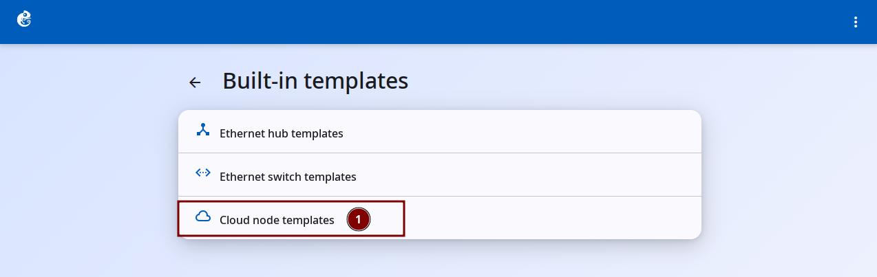
Click the "Built-in" option to enter.
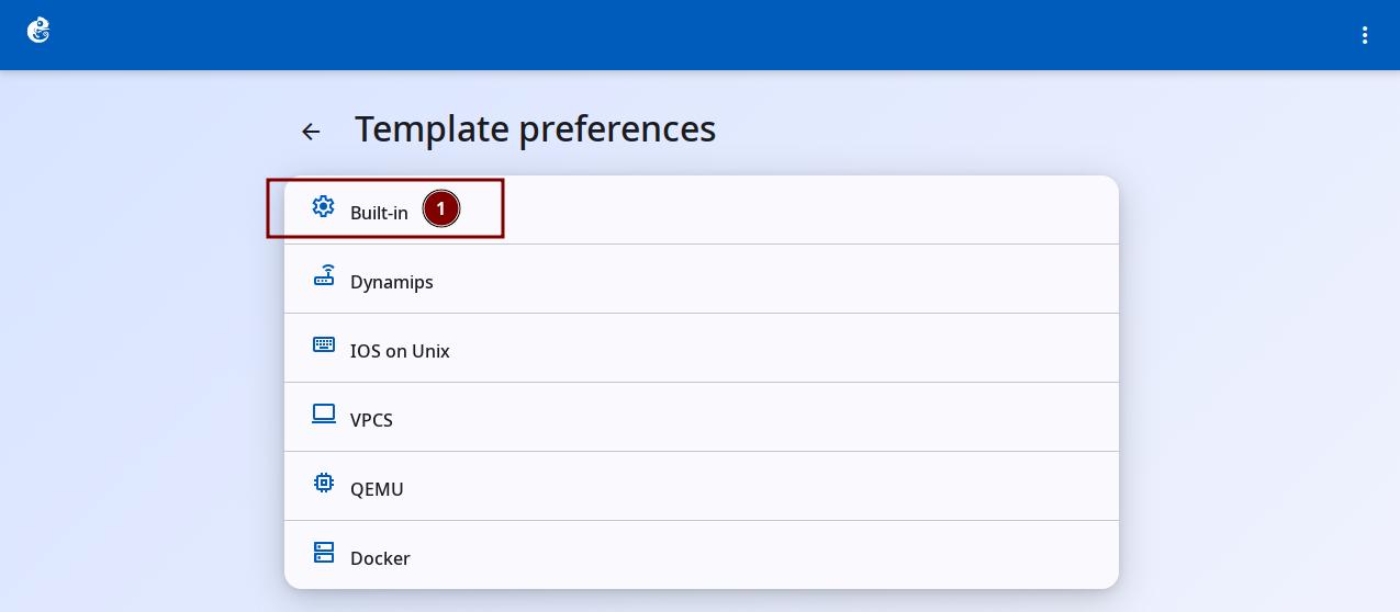
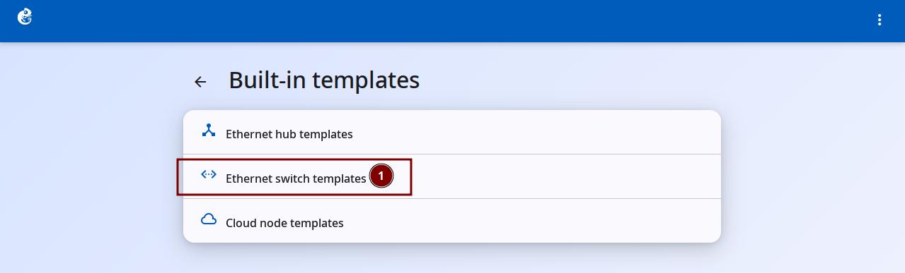
Built-in templates include these three types of network devices:
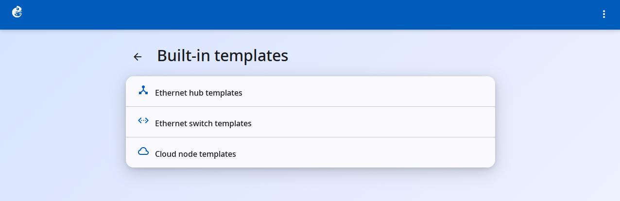
- Ethernet Hub
- Ethernet Switch
- Cloud Node
Ethernet Hub
Ethernet Hub is a built-in node type in GNS3. It simulates a simple physical layer (Layer 1) repeater Hub.
Main Features
| Property | Value |
|---|---|
| Category | switch |
| Default name format | Hub{0} |
| Default number of ports | 8 (Ethernet0 ~ Ethernet7) |
| Symbol | hub |
| Start/Stop | No (created and running, builtin node) |
| Console | Not supported |
How It Works
- Actual implementation: uses the Dynamips nio_bridge hypervisor command
- All ports are flat: no adapter concept, 8 ports are numbered 0-7 directly
- Port behavior: when the Hub receives data, it sends the data out through all ports except the incoming port (pure physical layer broadcast)
- Supports PCAP capture: you can start and stop packet capture on a single port
Uses
Ethernet Hub is mainly used for teaching and network experiments. It simulates the behavior of old Ethernet Hubs (shared bandwidth, collision domain). Compared to Ethernet Switch, it helps students understand concepts like collision domains and CSMA/CD. For most users, it works out of the box, no need to add it manually.
Create a Template
These templates already exist in the system by default. You usually do not need to create them manually.
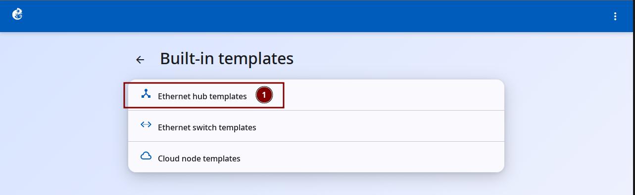
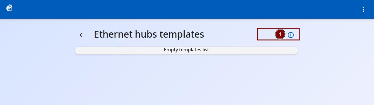
Click the "Ethernet Hub Templates" option to enter.
Click the + button at the top right to add a new template.
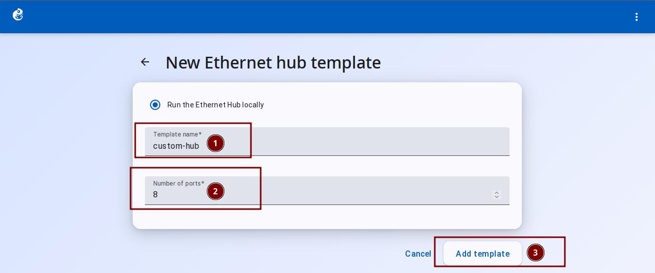
Enter the Template Name and Number of Ports, then click "Add Template" to finish.
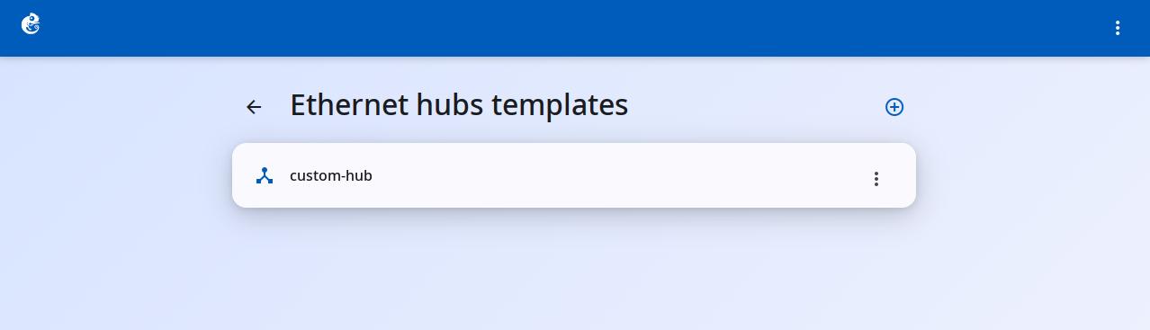
After creation, you can see the new template in the list.
Click the three-dot button on the right to choose Delete or Edit.
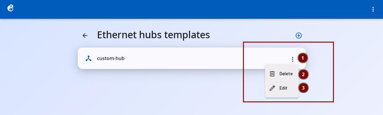
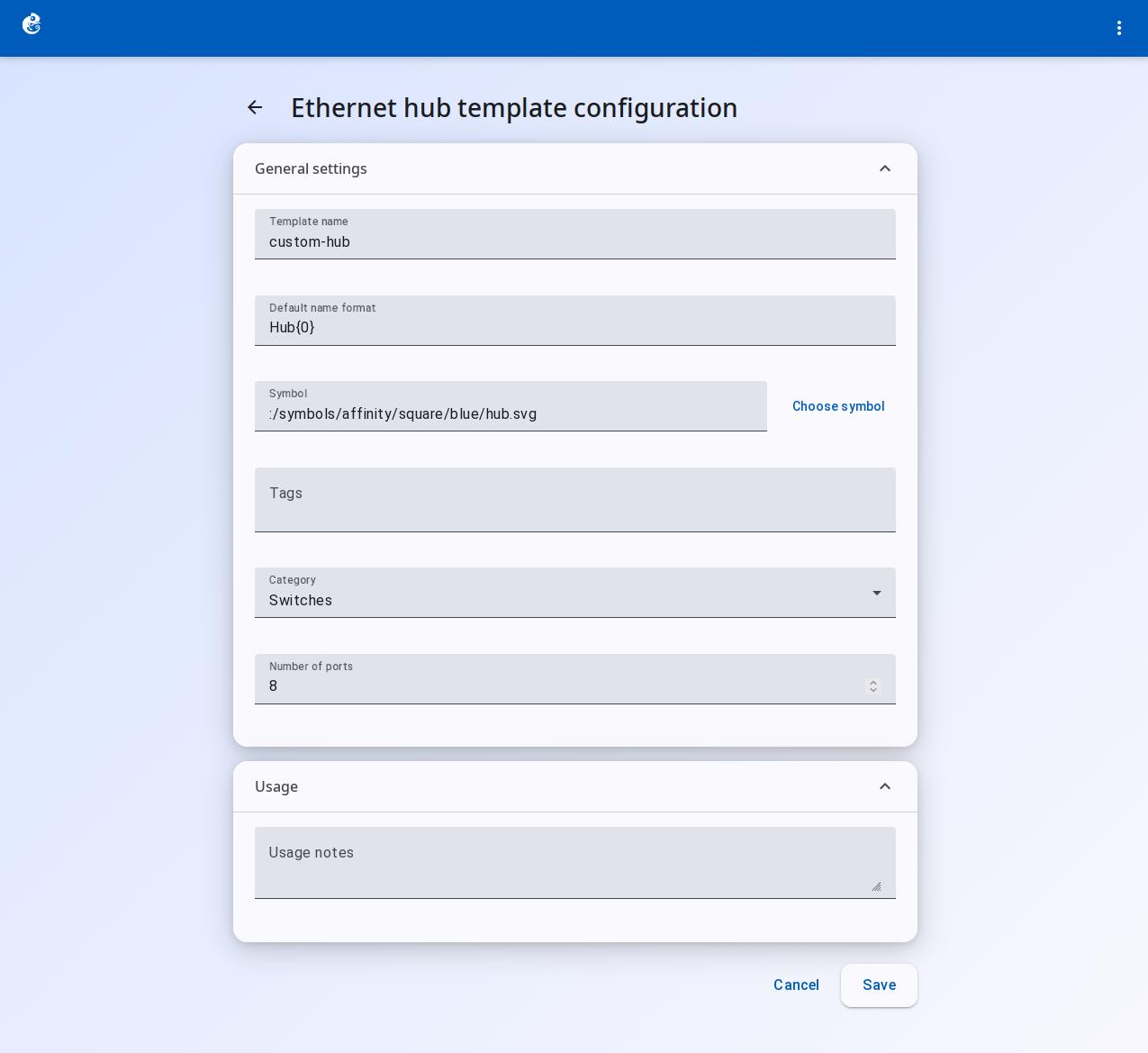
Click Edit to open the editing screen. You can set these options:
Template Name
Default Name Format
Symbol (device icon)
Choose Symbol
Tags
Category
Number of Ports
Usage
After changes, click the "Save" button at the bottom right.
Ethernet Switch
Ethernet Switch is a built-in Layer 2 switch node in GNS3. It uses the Dynamips hypervisor ethsw command. It supports VLANs and port mode configuration.
Differences from Ethernet Hub
| Feature | Hub | Switch |
|---|---|---|
| Layer | Physical layer (L1) | Data link layer (L2) |
| VLAN | Not supported | Supports Access / dot1q / QinQ |
| MAC learning | Broadcast to all ports | Dynamips keeps a MAC table inside |
| Collision domain | Shared (one collision domain) | Each port has its own collision domain |
Default Configuration
- Number of ports: 8 (Ethernet0 ~ Ethernet7)
- Port type: all access, VLAN 1
- Name format:
Switch{0} - Type: builtin node, created and running, cannot be stopped or started
Port Modes
You can set the behavior of each port with ports_mapping. Three modes are supported:
1. Access Port
Belongs to a single VLAN. Usually connects end devices (PCs, servers).
2. dot1q Port (802.1Q trunk port)
Lets multiple VLANs pass through. Sets a native VLAN.
3. QinQ Port (802.1ad provider trunk)
Double-layer VLAN tagging. Used in provider networks. You can set the outer ethertype.
Supported ethertype values:
| Value | Standard |
|---|---|
| 0x8100 | Standard 802.1Q (default) |
| 0x88A8 | Provider 802.1ad (QinQ) |
| 0x9100 | Old QinQ |
| 0x9200 | Old QinQ |
Port settings are applied to the Dynamips hypervisor automatically when a link is created (NIO binding).
Limitations
- Cannot start/stop/suspend/restart — builtin node, created and running
- Console not available — although there is a console_type property, telnet will say it is not available
- Layer 2 only — does not support Layer 3 routing, STP, or other advanced switch features
- Port configuration is on the compute side — the controller only sees a flat port list. VLAN/type information only works on the Dynamips level
Create a Template
These templates already exist in the system by default. You usually do not need to create them manually.
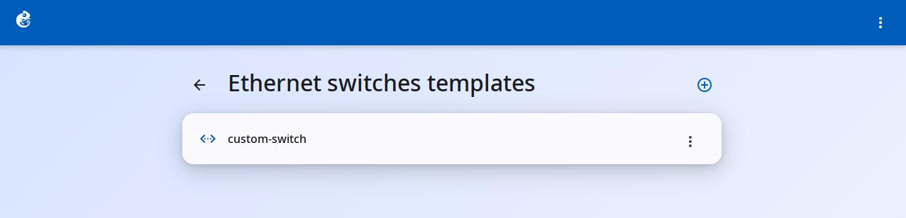
Click the "Ethernet Switch Templates" option to enter.
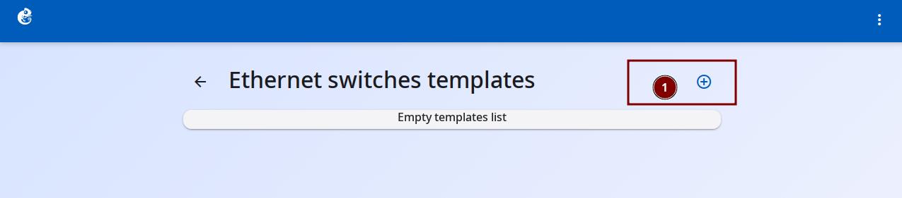
Click the + button at the top right to add a new template.
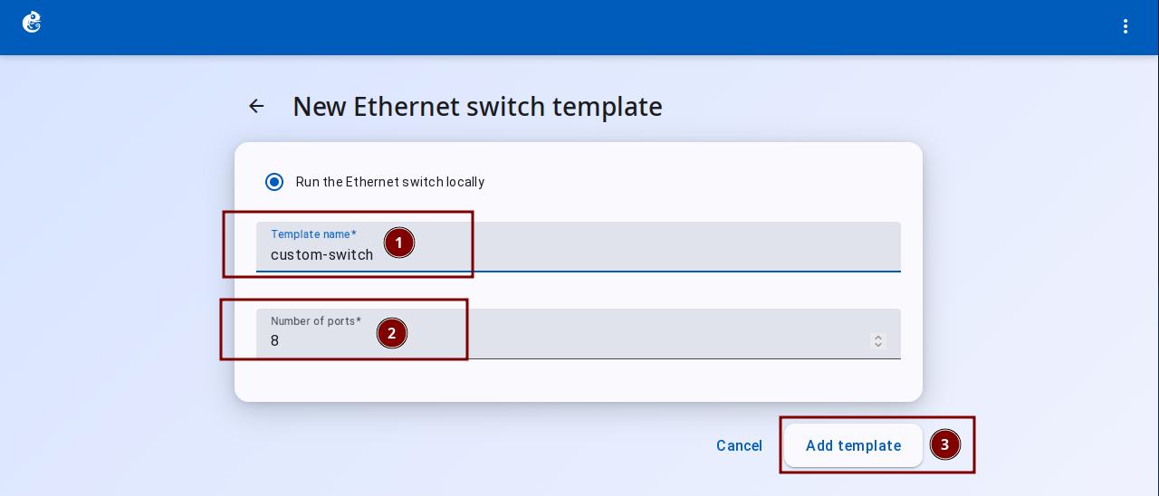
Enter the Template Name and Number of Ports, then click "Add Template" to finish.
After creation, you can see the new template in the list.
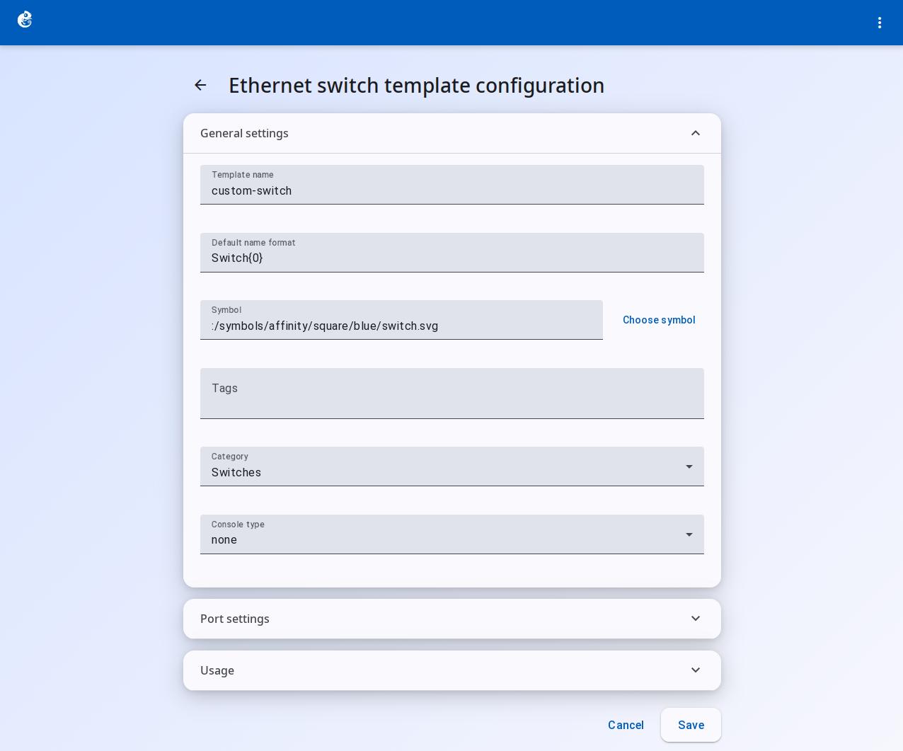
Click Edit to open the editing screen:
General Settings
- Template Name
- Default Name Format
- Symbol
- Choose Symbol
- Tags
- Category
- Console Type
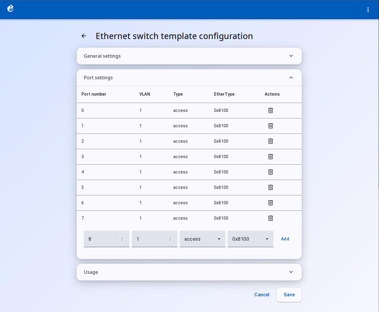
Port Settings
Port Number
VLAN (VLAN ID)
Type (port type)
EtherType
Actions
After changes, click the "Save" button at the bottom right.
Cloud Node
Cloud node is a built-in node in GNS3 that bridges to the host machine network. It belongs to the guest category. Name format is Cloud{0}.
Main Purpose
Cloud lets virtual devices in your topology talk to the host network (or the host itself). It is a network bridge point. It maps links in the topology to real network interfaces on the host machine.
Three Port Types
Cloud supports three port mapping methods for different connection scenarios:
1. Ethernet Port (most common)
Directly binds to a physical or virtual network card on the host.
2. TAP Port
Binds to a TAP virtual interface on the host.
3. UDP Port
Directly sets a UDP tunnel endpoint (rarely used).
Auto Discovery of Interfaces
When you create a Cloud node without setting port mappings, the system fills in non-special interfaces from the host automatically. It excludes these types:
lo,vmnet*,vboxnet*,docker*,lxcbr*,virbr*ovs-system,veth*,fw*,p2p*,bridge*vmware*,virtualbox*,gns3*,*-nic
Differences from NAT Node
| Feature | Cloud | NAT |
|---|---|---|
| Bridges to | Any host interface | Default virbr0 (Linux) |
| Number of ports | Configurable, many | Fixed single nat0 port |
| Interface customization | Free to choose | Fixed |
| Port mapping can be changed | Yes | Read-only |
| Use | Flexible bridge to a specific network | Quick NAT internet access |
Limitations
- Does not support Stop/Suspend — builtin node, can only Start (actually created and running)
- Cloud-to-Cloud direct connection is not allowed — controller/link.py blocks this type of connection
- Needs privileges — Ethernet type on Linux needs root permission for raw sockets or TAP devices
- macOS does not support Wi-Fi adapter bridging
Cloud Node Console
The Cloud node itself cannot be operated through a console (it is not a router/switch). Although the Schema has remote_console_* fields (like remote_console_type, remote_console_host, remote_console_port), the database stores them, and the API sends them, the server does not actually use these fields. They are like reserved placeholder fields or old unused properties. The Cloud console is not available.
Create a Template
These templates already exist in the system by default. You usually do not need to create them manually.
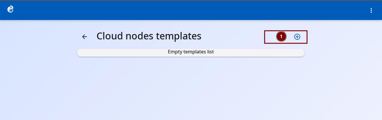
Click the "Cloud Node Templates" option to enter.
Click the + button at the top right to add a new template.
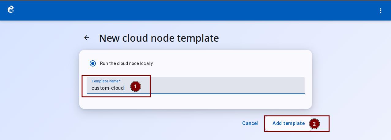
Enter the Template Name, then click "Add Template" to finish.
After creation, you can see the new template in the list.
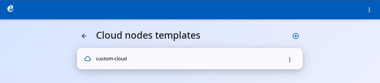
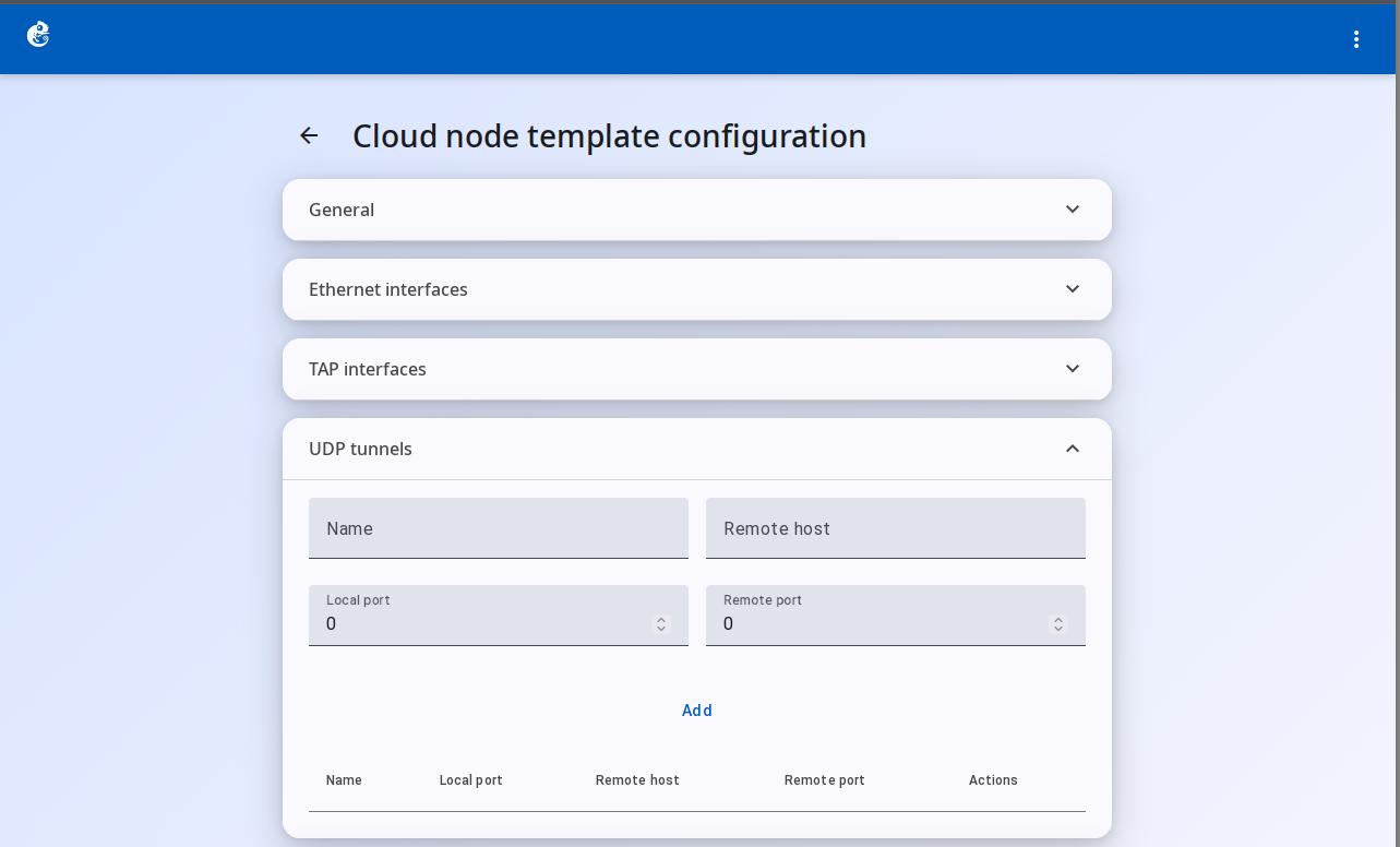
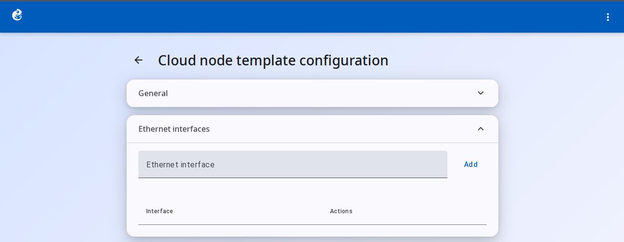
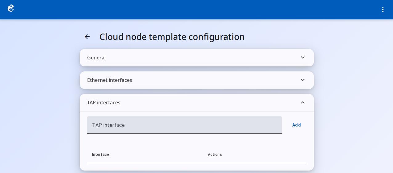
Click Edit to open the editing screen:
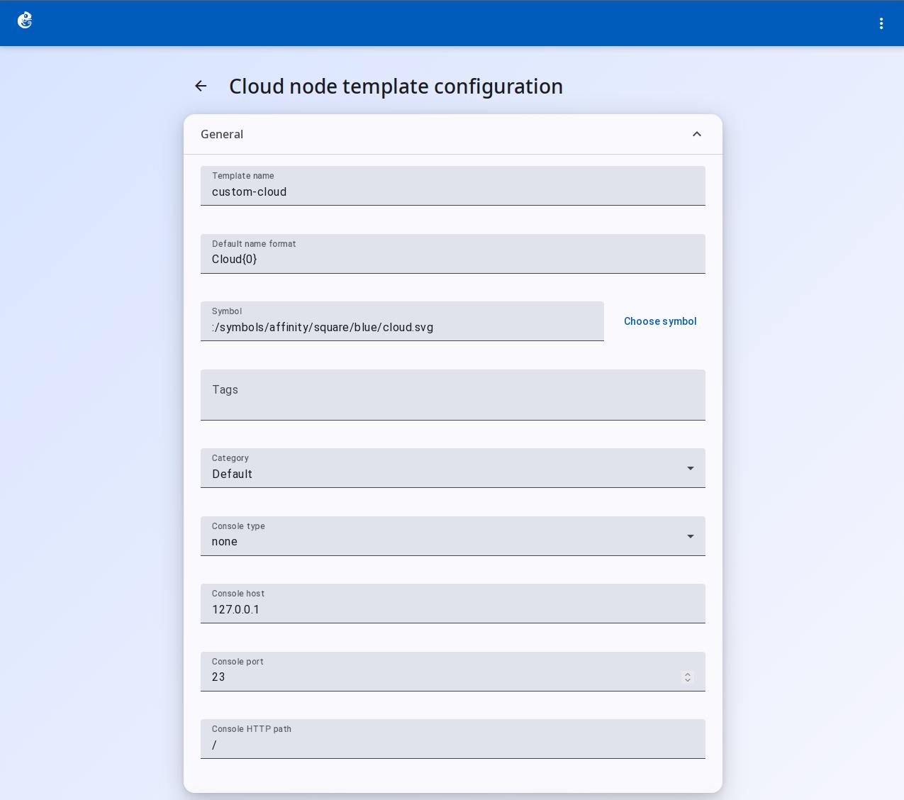
General Settings
Template Name
Default Name Format
Symbol
Choose Symbol
Tags
Category
these fields are not actually used
Console Type
Console Host
Console Port
Console HTTP Path
Ethernet Interfaces — no data in the template. You need to add a node in the project and then configure it.
TAP Interfaces — add TAP interface names.
UDP Tunnels — create a UDP tunnel to connect to a specific port on a remote host.